

Microarchitecture
Microarchitecture connects circuits and ISA together. ISA = Instruction Set Architecture
ISA specifies what hardware does, but not how
- ISA defines the instruction code
Microarchitecture specifies how it does it
- Microarchitecture determine how it work it

- The ISA is the interface of a processor as seen by an assembly language programmer or compiler writer
- Micro-architecture transfers the ISA into an implementation
- For a given ISA, there might be many different microarchitectures
- An architecture is a collection of circuits connected
Von Neumann architecture

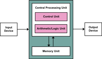
- Memory
- CPU
- Register
- ALU
- CU
- I/O

- Memory stores not only data, but coded instructions that make up a computer program
- CPU fetches and executes – interprets - successive instructions of the program
- Program is simply data for the interpreter – as in a Universal Turing Machine!
- Single expandable resource pool – main memory
- constrains both data and program size

Memory
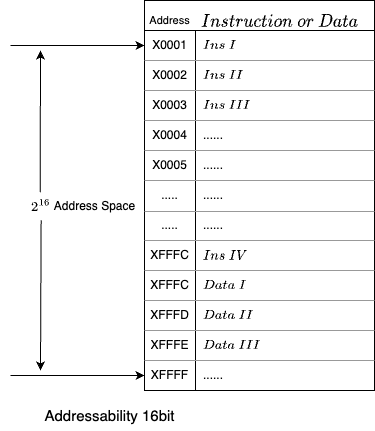
- Address space
- means: there are
block
- means: there are
- Addressability
- Each block store 16-bit instruction
- Each block represent by a Hexadecimal code
- x0000
- x0001
- ....
- Address 逐行递增
- Each block represent by a Hexadecimal code
- Memory is store element
- Basic Operations
- LOAD
- read a value from a memory location
- STORE
- write a value to a memory location
- write a value to a memory location
- LOAD
Interface to Memory
- MAR: Memory Address Register (D flip-flops)
- MDR: Memory Data Register (D flip-flops)

- To read a location (A):
- Write the address (A) into the MAR.
- Send a “read” signal to the memory.
- Read the data from MDR.
- To write a value (X) to a location (A):
- Write the data (X) to the MDR.
- Write the address (A) into the MAR.
- Send a “write” signal to the memory.
CPU
- The brain of the computer
- It is the part that actually executes the machine instructions
- Inside the CPU
- Data path
- Registers
- Control Path
- IR (instruction register), PC (program counter), FSM (finite state machine)
- Data path
Register Register File
- Register is store element
- Achieved by D filp-flop
- 8 Register
- Each register represent by 3 bit to record its address
- 000
- 001
- 010
- ...
- 110
- 111
- 000
- Each register represent by 3 bit to record its address
- Source Register 1
- Source Register 2
- Destination Register
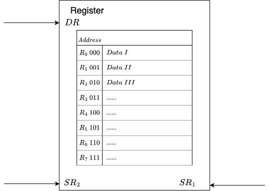
- Why register? Closer to processing unit, allow quicker access to intermediate results instead of going to memory
ALU Arithmetic Logic Unit
Perform arithmetic and logic operations (AND, NOT, ADD) on values stored in registers
- ADD
- AND
- NOT A
- PASS A
CU
Control Unit: a finite state machine coordinates execution of the program  IR Get the Instruction from Memory through PC's address
- PC Program Counter
- It stores the next instruction address
- In each clock, PC+=1
- In x86 architecture also called IP Instruction Pointer
- IR Instruction Register
- Current Instruction
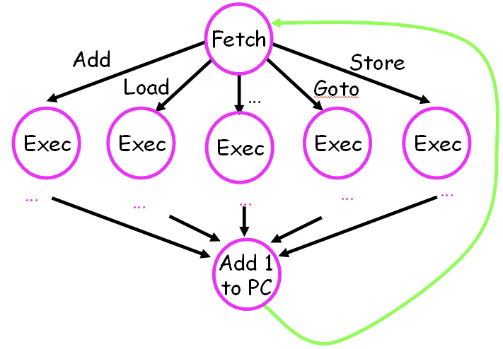
- Control Unit as a Finite State Machine
I/O
- Devices for getting data into and out of memory
- Each device has its own interface, usually a set of registers like the memory’s MAR and MDR
- keyboard: data register (KBDR) and status register (KBSR)
- console: data register (DDR) and status register (DSR)
Instruction
- The instruction is the most basic unit of computer processing.
- One instruction specifies two things:
- opcode: operation to be performed
- operands: data/locations to be used for operation
- An instruction is encoded as a sequence of bits (just like data!)
- Control unit interprets instruction
- A computer’s instructions and their formats is known as its Instruction Set Architecture (ISA).
Lc-3's ADD Instruction
- opcode: 0001
- steering bit IR[5]
If IR[5]=0
ADD DST SR1 000 SR2
0001 xxx xxx 000 xxx- operands: Src1,Src2,Dst
- Src1+Src2->Dst
If IR[5]=1
ADD DST SR1 1 xxxxx
0001 xxx xxx 1 xxxxx- operands: Src1,Dst,xxxxx
- Src1+xxxxx->Dst
LC-3's LDR Instruction
opcode: 0110
operands: Src,Dst
Load the value in memory location Src into register Dst
Move [Base + Offset] to Dst
Load memory content at address (R3 + 6) to R2
LDR DST SRC offset
0110 xxx xxx xxxxxx
Instruction processsing
- Fetch
- Decode
- Evaluate Address
- Fetch operands
- Execute
- Store result

Fetch
PC-MAR-MDR-IR
Load next instruction (at address stored in PC) from memory into Instruction Register (IR).
- Load contents of PC into MAR.
- Send “read” signal to memory.
- Read contents of MDR, store in IR.
Then increment PC, so that it points to the next instruction in sequence.
- PC becomes PC+1.
Decode
First identify the opcode.
- In LC-3, this is always the first four bits of instruction.
- A 4-to-16 decoder asserts a control line corresponding to the desired opcode.
Evaluate Address 计算地址
- For instructions that require memory access, compute address used for access.
- Examples:
- add offset to base register (as in LDR)
- add offset to PC (or to part of PC)
Fetch Operands
- Obtain source operands needed to perform operation.
- Examples:
- load data from memory (LDR)
- read data from register file (ADD)
Execution
- Perform the operation, using the source operands.
- Examples:
- send operands to ALU and assert ADD signal
- do nothing (e.g., for loads and stores)
Store
- Write results to destination (register or memory)
- Examples:
- result of ADD is placed in destination register
- result of memory load is placed in destination register
- for store instruction, data is stored to memory
Changing the Sequence of Execution
- In the FETCH phase, PC is incremented by 1 automatically (counter)
- Other Sequence
- if-then, loop, function call
- Achieved by special instruction that changes the content of PC
- Jumps (unconditionals)
- Branches (conditional)
LC-3's Jump Instruction
Set the PC to the value obtained by adding an offset to a register.
JMPR 000 BASE offset
1100 000 011 000110
Add the value of 6 (offset) to the contents of R3 (Base),and load the result into the PC
This becomes the address of the next instruction to fetch.
Driving Force: the Clock
The clock is a signal that keeps the control unit moving.
At each clock “tick,” control unit moves to the next machine cycle -- may be next instruction or next phase of current instruction.
Stopping the Computer
- Stopping the instruction cycle requires stopping the clock
Instruction summary
- Three basic kinds of instructions:
- computational instructions (ADD, AND, …)
- data movement instructions (LD, ST, …)
- control instructions (JMP, BRnz, …)
Micro-Architecture Level
- Computer = processing unit + memory system + I/O
- Processing unit = control + data path
- Control = FSM Finite state machine
- Inputs = machine instruction,datapath condition
- Outputs = register transfer control signal, ALU operation codes
- Instruction interpretation = instruction fetch, decode, execute, write
- Datapath = function units +registers
- All logic used to process information
- Functional units = ALU, multipliers,dividers...
- Register = PC program counter, IR instruction register, storage registers
- All logic used to process information
- Control = FSM Finite state machine
- Processing unit = control + data path